Getting the most from Ground Source Heating
Part 2: Underfloor Heating Design
Claims for Ground Source heating efficiencies are often quite vague to allow for the variations in each installation. It is difficult to compare installations and to know what features the buyer should look for and what they may cost.
For this reason we plan to document our methods well and give the reasoning so that others may be able to build on our experiences and criticise the science involved.
The efficiency of a ground source installation is measured by its COP value. This is the ratio of the energy input in the form of electricity to the heat output within the building. This ratio is affected by the efficiency of each component in the system but we suspect that some will be more important than others.
Breaking the problem into two halves we want to get the best from the ground loop system by good design and controlled operation. Our DIY ground loop construction is the subject of a separate leaflet in Part 1.
Underfloor Heating
In general it is agreed that the lower the temperature of the output from the heat pump can be set the more efficiently it can operate. The worst option is to use existing radiators, but even in these cases satisfactory installations have been achieved. A gas or oil fired system will heat the house radiators to over 50 degrees during the initial warm up period running at 4 times the output of the heat pump so we must achieve comfort by slower heating in a better insulated space for a longer time.
We are planning to improve the insulation of the existing house as much as we can but this leaflet will concentrate on the floor itself.
We have solid floors which would be expensive to dig up. We were quoted £3000, which did not seem too bad but we would need to excavate below, reinstate the damp course and build up the insulation below the screed so the whole job would be nearer £10,000. The only alternative appears to be to lay insulation, pipework and a screed on top of the existing floor. If this is kept below 50mm in total it should not reduce our 2.4 metre ceilings too much but the doorways will need some attention.
Our exploration of underfloor heating systems has covered 2 years, from the time we saw the Polypipe stand and the Eco-Build Show at Earls Court to the present. Polypipe were taken over by Upenor who quoted us £10,000 for the materials alone for our 4 bedroom house. They extolled the virtues of their multi wall pipe but the most expensive was the aluminium trays which were to be laid on the floor to hold the pipe which were over half the total cost.
A quote from Ice Energy was more reasonable at about £5000. This was still more than we could afford. They would prepare polystyrene forms into which the pipes would be pressed. This would provide the insulation below the pipework included in the price.
On our latest visit to the Eco-Build show we found the Superfoil stand showing their SFUF material used as insulation directly beneath underfloor heating pipes. This consists of 13 layers of insulation and foils which compress to 5 mm thickness under the pipes.
Above the pipes
The heat reaching the room compared with the heat going back to the ground under the floor will depend on the resistance of the Superfoil SFUF compared with the resistance of the materials above the pipes. Thick carpets and thick wooden floors are discouraged but opinions varied considerably on the best material for conducting the heat up into the room.
Ceramic tiles are known to be good so we planned these in from the start. We have now found some attractive wood looking tiles which we think will be great for the lounge and dining room and some very large creamy tiles for the hall and kitchen. Betty likes tiles because they are easy to clean and maintain in our little place in the Canaries.
What should we use between the pipes and the tiles? Screed would have to be thick. Marine ply was suggested but would have to be thin to avoid insulating and then would risk distorting with the heating and cooling.
Then we found Knauf Brio 23 screed board. It has been designed by Knauf to be thermally transparent ( which I think must mean it is highly conductive). It is thicker than we had hoped at 23mm but seems to be the best option. It is rather expensive but fits together without adhesive to form a true base for the tiles. However I have not yet been able to get more technical data on its use.
Round the pipes
As Knauf Brio is so new I thought it worth while to try to work out how the heat could flow most easily from the pipes to the Brio underside. Sand round the pipes seemed to be the only option on display at the Eco-Build exhibition. This seemed to have the disadvantage that it would make better contact with the surface below than with the surface above so would encourage the heat downwards. An adhesive applied to the top of the pipes might be better as it could even out the point loads on the pipes caused by any unevenness and would transmit heat upwards leaving insulating air around and below. I have asked almost everyone which adhesives were good conductors of heat but cannot find any data on this so I devised my own experiment.
My Experiment (1)
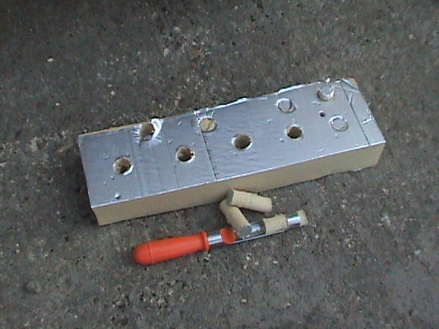
I used an apple corer to take out a core of Cellotex every 3cms in a block of Cellotex 75mm thick. I placed this on top of a radiator and poured into it 4 samples of materials which might be suitable. I used Wickes Acrylic Flexible Frame Sealer, B & Q All Purpose Silicone, Wickes Panel Adhesive, and Dow Corning Glazing Seal. I allowed these to dry and as they started to set pressed the probe of a digital thermometer down into the core to leave a form to make good contact when the adhesive was fully dry. I then left the adhesives for one day to dry.
Before testing I cut a cardboard shield to fit round the Cellotex to reduce the warm air convecting from the radiator affecting the readings in the cores.
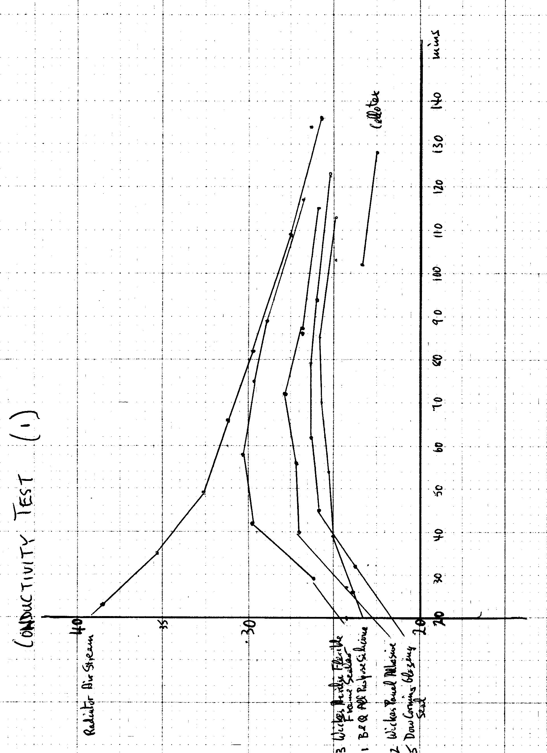
For the first test I heated the radiator to full heat and then switched off the heating. As the radiator cooled I inserted the digital thermometer into each of the forms in the cores and waited until a constant reading was achieved for 20 seconds. This was then recorded, with the time, and repeated for each core. Two readings were taken by the probe pressed into the Cellotex for comparison.
The readings were plotted using graph paper because the points varied in two dimensions and were difficult to represent in Excel. They showed a clear winner was Wickes Acrylic Flexible Frame Sealer as it quickly gained a temperature close to that of the air close to the radiator and within one hour virtually matched that temperature. Second came the panel adhesive and below them came the 2 silicones.

One problem observed was that the Wickes Acrylic had not fully set by the time the readings were taken. The tip of the probe came out with a smear of adhesive on it. Were the good results just because wet adhesive was a very good conductor of heat or because the wet contact with the probe was a better contact? Were any of the other adhesives conducting better now than they would when fully cured?
If dry sand was popular as a filler round the pipe was there a good reason for this? My results should be compared with some results for dry sand in similar conditions. The next test was designed to answer some of these questions.
Conductivity Test (2)
The above test was repeated with the following changes. A test of sand was performed by dropping a little wet cement in the bottom of a core. When this was dry the core was filled with sand. Without the cement the sand would have run though onto the floor.
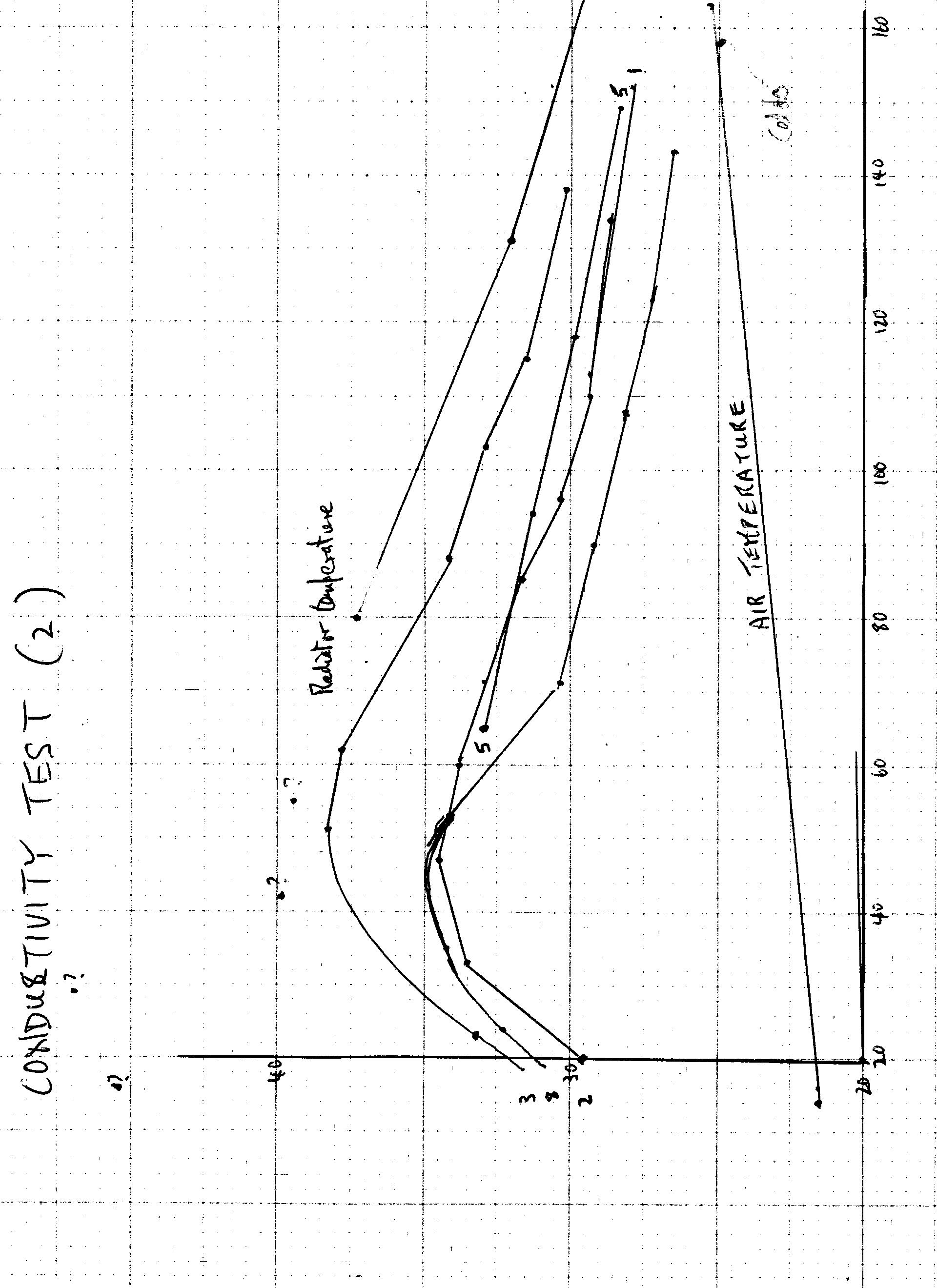
It was decided to test only the best 2 materials from the earlier test but the silicones were still in place. When one of these was checked 40 minutes after the start it was found to be very close to the panel adhesive so it was included from then on. Air temperature away from the radiator was taken before and after the experiment and the difference of 3.5 degrees C was quite significant.
The Cellotex temperature was found to be close to the air temperature.
Once again the Wickes Acrillic Flexable Frame Sealer proved the best but did not approach nearer than 2 degrees to the radiator temperature in 70 minutes cooling compared with 0.5 degrees before. It was clearly continuing to cure and could well perform worse than the others when fully cured.
The panel adhesive too gained temperature quickly but when the heat source was cooling it did no better than the two silicones.
The sand did worst of all as it maintained a temperature difference of 5 degrees from the heat source compared with 3 degrees for the other materials.
When it was noticed that dry sand (8) was doing badly it was also noticed that the probe did not sink as easily into the sand as it did into the prepared hole in the other materials. A modification was then made to scoop out the sand and replace it round the probe for each reading thus ensuring that the probe was fully covered by the sand and not taking any reading from the atmosphere. This made no discernible difference.
Conclusion
The limitations of the equipment and the method make any conclusion of little value. I hope it will stimulate others to study the problem more accurately and I plan to repeat the comparisons with some of the materials in a real application in my home.
The quality of the conductive contact will eventually be more important than the conductivity of the material as the thickness of the material over the pipes will be between 1 and 2 mm at most. Silicones achieve this high contact level and are unlikely to fracture or fissure.
My inclination is to prefer the Dow Corning Glazing Seal. In the last test it was close to the best and its steady performance as the source cooled suggested that it would not deteriorate with further curing. This is surprising however as one would expect a glazing seal to be formulated as an insulator.
The poor performance of dry sand leads me to question its use to improve conductivity underground to the collector pipes. Possibly it will always be wet it the Winter when the heating is required and so a better conductor.
I hope others will provide some better data before September when I have to put theory into practice. I have retained the cores so they could be sliced for laboratory tests.
Malcolm Crocker 28/06/09
01865 351984